On this tutorial we’re going to discover the chances of making a {custom} materials utilizing shaders based mostly on built-in Three.js supplies with React Three Fiber.
Overview
We’ll study:
- hook right into a built-in Three.js materials to change it the way in which we wish
- displace vertices of a mesh to get a surprising form
- make lighting respect this new form
- As a bonus, we’ll discover ways to repair the shadows after the geometry displacement
This tutorial requires:
- Fundamental information of React, together with parts, state, and props.
- Fundamental understanding of Three.js, together with fundamental ideas of 3D rendering, geometries, and supplies.
Prepared? Let’s get began!
Step 1: Fundamental setup
First, we have to arrange our venture with R3F and create a fundamental scene with a sphere.
import React, { Suspense } from 'react';
import { OrbitControls } from '@react-three/drei';
import { Canvas } from '@react-three/fiber';

const Experiment = () => {
    return (
        <>
            <mesh>
                <icosahedronGeometry args={[1.3, 200]} />
                <meshPhysicalMaterial
                    roughness={0.56}
		            metalness={0.76}
		            clearcoat={0}
		            ior={2.81}
		            iridescence={0.96}
                />
            </mesh>
            <ambientLight />
            <directionalLight depth={5} place={[-2, 2, 3.5]} />
        </>
    );
};

const Expertise = () => {
    return (
        <div className="canvas-wrapper">
            <Canvas
                digital camera={{
                    place: [0, 0, 5],
                    fov: 45,
                    close to: 0.1,
                    far: 1000,
                }}
                gl={{ alpha: false }}
            >
                <Experiment />
                <OrbitControls />
            </Canvas>
        </div>
    );
};

export default Expertise;
On this code:
- We arrange a fundamental React element
Experimentthat creates a sphere utilizingicosahedronGeometryand a bodily materials with some properties. - We add ambient and directional lighting to the scene.
- The
Expertiseelement units up theCanvaswith a digital camera and orbit controls for interplay.
Nothing fancy right here, we simply created a fundamental canvas, arrange lighting, and added a sphere to the scene. It will function the muse for our additional modifications.
Step 2: Refactor to make use of three-custom-shader-material
MeshPhysicalMaterial is essentially the most superior built-in materials in Three.js. How can we modify the fabric’s shader with out dropping its present performance?
Historically, that is accomplished utilizing the fabric’s onBeforeCompile methodology. This methodology takes the present shaders as strings, which we will change with our code. It appears one thing like this:
materials.onBeforeCompile = (shader) => {
    shader.uniforms = {
        ...shader.uniforms,
        ...uniforms,
    };

    shader.vertexShader = shader.vertexShader
        .change(
            '#embrace <frequent>',
            `
            #embrace <frequent>
            // your code
            `,
        )
        .change(
            '#embrace <project_vertex>',
            `
            #embrace <project_vertex>
            // your code
            `,
        );
};
Nonetheless, this strategy will be inconvenient and unreadable. As a substitute, we’ll use the wonderful library THREE-CustomShaderMaterial.
import React, { Suspense, useRef } from 'react';
import { OrbitControls } from '@react-three/drei';
import { Canvas } from '@react-three/fiber';
import CustomShaderMaterial from 'three-custom-shader-material';
import { MeshPhysicalMaterial } from 'three';

const Experiment = () => {
    const materialRef = useRef(null);

    return (
        <>
            <mesh>
                <icosahedronGeometry args={[1.3, 200]} />
                <CustomShaderMaterial
                    ref={materialRef}
                    silent
                    baseMaterial={MeshPhysicalMaterial}
                    roughness={0.56}
		            metalness={0.76}
		            clearcoat={0}
		            ior={2.81}
		            iridescence={0.96}
                />
            </mesh>
            <ambientLight />
            <directionalLight depth={5} place={[-2, 2, 3.5]} />
        </>
    );
};

...
The outcome is identical, however now we will use the library to rewrite components of the shader. Create empty vertex.glsl and fragment.glsl recordsdata:
// vertex.glsl

void important {

}
// fragment.glsl
void important {
}Observe: We don’t assign values to the variables gl_Position and gl_FragColor immediately. As a substitute, we assign values to the variables anticipated by the library (later within the tutorial). An entire checklist of those variables will be discovered right here.
Step 3: Displace the Form within the Vertex Shader Chunk
Our process is to change the vertex positions based mostly on some sample, displacing them from the middle within the route of the conventional. We use the fragment shader to visualise this sample. Because the outcome must be used within the vertex shader, we write the code there and cross the outcome through various for visualization.
What we need to do:
- animate the sample to go up infinitely
- distort it with noise operate to offer it natural random look
- make fractions of this sample
- push the vertices outwards utilizing normals
Let’s begin with displaying the sample within the fragment shader:
// vertex.glsl

uniform float uTime;

various float vPattern;

//	Basic Perlin 3D Noise
//	by Stefan Gustavson (https://github.com/stegu/webgl-noise)
//
vec4 permute(vec4 x){return mod(((x*34.0)+1.0)*x, 289.0);}
vec4 taylorInvSqrt(vec4 r){return 1.79284291400159 - 0.85373472095314 * r;}
vec3 fade(vec3 t) {return t*t*t*(t*(t*6.0-15.0)+10.0);}

float cnoise(vec3 P){
  vec3 Pi0 = flooring(P); // Integer half for indexing
  vec3 Pi1 = Pi0 + vec3(1.0); // Integer half + 1
  Pi0 = mod(Pi0, 289.0);
  Pi1 = mod(Pi1, 289.0);
  vec3 Pf0 = fract(P); // Fractional half for interpolation
  vec3 Pf1 = Pf0 - vec3(1.0); // Fractional half - 1.0
  vec4 ix = vec4(Pi0.x, Pi1.x, Pi0.x, Pi1.x);
  vec4 iy = vec4(Pi0.yy, Pi1.yy);
  vec4 iz0 = Pi0.zzzz;
  vec4 iz1 = Pi1.zzzz;

  vec4 ixy = permute(permute(ix) + iy);
  vec4 ixy0 = permute(ixy + iz0);
  vec4 ixy1 = permute(ixy + iz1);

  vec4 gx0 = ixy0 / 7.0;
  vec4 gy0 = fract(flooring(gx0) / 7.0) - 0.5;
  gx0 = fract(gx0);
  vec4 gz0 = vec4(0.5) - abs(gx0) - abs(gy0);
  vec4 sz0 = step(gz0, vec4(0.0));
  gx0 -= sz0 * (step(0.0, gx0) - 0.5);
  gy0 -= sz0 * (step(0.0, gy0) - 0.5);

  vec4 gx1 = ixy1 / 7.0;
  vec4 gy1 = fract(flooring(gx1) / 7.0) - 0.5;
  gx1 = fract(gx1);
  vec4 gz1 = vec4(0.5) - abs(gx1) - abs(gy1);
  vec4 sz1 = step(gz1, vec4(0.0));
  gx1 -= sz1 * (step(0.0, gx1) - 0.5);
  gy1 -= sz1 * (step(0.0, gy1) - 0.5);

  vec3 g000 = vec3(gx0.x,gy0.x,gz0.x);
  vec3 g100 = vec3(gx0.y,gy0.y,gz0.y);
  vec3 g010 = vec3(gx0.z,gy0.z,gz0.z);
  vec3 g110 = vec3(gx0.w,gy0.w,gz0.w);
  vec3 g001 = vec3(gx1.x,gy1.x,gz1.x);
  vec3 g101 = vec3(gx1.y,gy1.y,gz1.y);
  vec3 g011 = vec3(gx1.z,gy1.z,gz1.z);
  vec3 g111 = vec3(gx1.w,gy1.w,gz1.w);

  vec4 norm0 = taylorInvSqrt(vec4(dot(g000, g000), dot(g010, g010), dot(g100, g100), dot(g110, g110)));
  g000 *= norm0.x;
  g010 *= norm0.y;
  g100 *= norm0.z;
  g110 *= norm0.w;
  vec4 norm1 = taylorInvSqrt(vec4(dot(g001, g001), dot(g011, g011), dot(g101, g101), dot(g111, g111)));
  g001 *= norm1.x;
  g011 *= norm1.y;
  g101 *= norm1.z;
  g111 *= norm1.w;

  float n000 = dot(g000, Pf0);
  float n100 = dot(g100, vec3(Pf1.x, Pf0.yz));
  float n010 = dot(g010, vec3(Pf0.x, Pf1.y, Pf0.z));
  float n110 = dot(g110, vec3(Pf1.xy, Pf0.z));
  float n001 = dot(g001, vec3(Pf0.xy, Pf1.z));
  float n101 = dot(g101, vec3(Pf1.x, Pf0.y, Pf1.z));
  float n011 = dot(g011, vec3(Pf0.x, Pf1.yz));
  float n111 = dot(g111, Pf1);

  vec3 fade_xyz = fade(Pf0);
  vec4 n_z = combine(vec4(n000, n100, n010, n110), vec4(n001, n101, n011, n111), fade_xyz.z);
  vec2 n_yz = combine(n_z.xy, n_z.zw, fade_xyz.y);
  float n_xyz = combine(n_yz.x, n_yz.y, fade_xyz.x);
  return 2.2 * n_xyz;
}

// It is like mod() operate, however "clean" (thanks, captain!), with no speedy bounce to 0
float smoothMod(float axis, float amp, float rad) {
    float prime = cos(PI * (axis / amp)) * sin(PI * (axis / amp));
    float backside = pow(sin(PI * (axis / amp)), 2.0) + pow(rad, 2.0);
    float at = atan(prime / backside);
    return amp * (1.0 / 2.0) - (1.0 / PI) * at;
}

// We gonna use this operate a number of occasions
float getDisplacement(vec3 place) {
		// gonna be uniforms in a while
		float uFractAmount = 4.;
		float uDisplacementStrength = 0.57;
		float uSpeed = 1.1;

    vec3 pos = place;
    pos.y -= uTime * 0.05 * uSpeed; // sample modifications in time, going up
    pos += cnoise(pos * 1.65) * uNoiseStrength; // place distortion with noise

    return smoothMod(pos.y * uFractAmount, 1., 1.5) * uDisplacementStrength;
}

void important() {
    float sample = getDisplacement(place);
    vPattern = sample; // cross the outcome to the fragment shader
}
// fragment.glsl
various float vPattern;
void important() {
vec3 colour = vec3(vPattern);
csm_FragColor = vec4(colour, 1.); // Utilizing `csm_FragColor` removes all of the shading. Use this just for debugging.
}The lighter the colour, the extra the vertex place shall be displaced at that time.
Subsequent, we have to replicate our sample within the vertex shader. We’d like the route through which we’ll shift the place. The traditional vector, which is perpendicular to the face, is ideal for this. Utilizing the conventional, we’ll push the vertex place outwards:
// vertex.glsl
...
void important() {
float sample = getDisplacement(place);
vPattern = sample;
csm_Position += regular * sample; // transfer place in accordance with regular
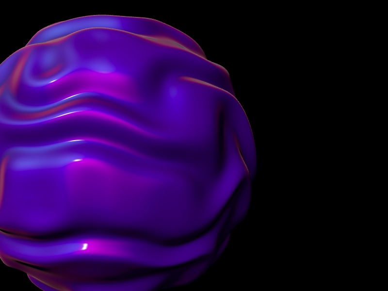
}Let’s add colour:
// Expertise.jsx

...

const uniforms = {
    uTime: { worth: 0 },
	uColor: { worth: new Shade('#af00ff') },
};

...
// fragment.glsl
various float vPattern;
uniform vec3 uColor;
void important() {
vec3 colour = vPattern * uColor;
csm_DiffuseColor = vec4(colour, 1.); // Restore shading utilizing `csm_DiffuseColor`
}It appears fairly good! However there is a matter. The shading doesn’t appear proper; one thing is off. The issue is that we modified the looks of the geometry, however the normals stay as if it have been a sphere. We have to recalculate them.
Step 4: Fixing the Shading
How will we try this? There’s a so known as “neighbours” approach. We have to discover two vectors going in the direction of neighbours which can be perpendicular to the conventional and one another. These are known as tangent and bitangent.
Let’s console.log the geometry.attributes:
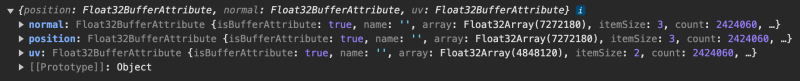
There isn’t a “tangent” attribute by default. Excellent news is that Three.js can calculate the tangent for us, and we will calculate the bitangent after. There’s a computeTangent() methodology on all geometries inheriting from BufferGeometry, so let’s use it. Fast word: in accordance with the docs, the computation is simply supported for listed geometries, and if place, regular, and uv are outlined. We do have the latter, however our geometry shouldn’t be listed proper now. We have to repair that. Three.js offers a bunch of utilities, considered one of which is the mergeVertices operate, which converts a non-indexed geometry to an listed one. Watch out: merging vertices is computationally intensive and should take a while.
Let’s use it and name “computeTangents()” afterwards:
...
import { MeshPhysicalMaterial, Shade, IcosahedronGeometry } from 'three';
import { mergeVertices } from 'three/examples/jsm/utils/BufferGeometryUtils';

...

// Refactor to make use of common Three.js code as an alternative of R3F primitive for comfort
const geometry = useMemo(() => {
    const geometry = mergeVertices(new IcosahedronGeometry(1.3, 200));
    geometry.computeTangents();

    return geometry;
}, []);

...

return (
    <>
        <mesh geometry={geometry}>
            <CustomShaderMaterial
                ref={materialRef}
                silent
                baseMaterial={MeshPhysicalMaterial}
                roughness={0.56}
		        metalness={0.76}
		        clearcoat={0}
		        ior={2.81}
		        iridescence={0.96}
            />
        </mesh>
        ...
    <>
);
Log the geometry attributes now:
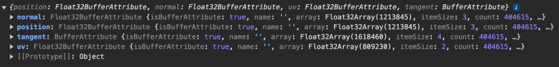
Nice, we now have the tangent! Now we’re able to calculate new normals.
// vertex.glsl

attribute vec4 tangent; // extract tangent

uniform float uTime;

various float vPattern;

...

void important() {
    float sample = getDisplacement(place); // base displacement sample
    vPattern = sample; // cross the outcome to the fragment shader

    vec3 biTangent = cross(regular, tangent.xyz);
    float shift = 0.01; // approximate distance to the neighbour
    vec3 posA = place + tangent.xyz * shift; // place of neighbour A
    vec3 posB = place + biTangent * shift; // place of neighbour B

    csm_Position += regular * sample;
    posA += regular * getDisplacement(posA); // making use of displacement to positionA
    posB += regular * getDisplacement(posB); // making use of displacement to positionB

    // To calculate route between two vectors,
	// we should always subtract the vacation spot from the origin,
	// then normalize it
	// Ensure to make use of `csm_Position` as an alternative of plain `place`

    vec3 toA = normalize(posA - csm_Position);
    vec3 toB = normalize(posB - csm_Position);

    csm_Normal = normalize(cross(toA, toB)); // recalculated regular
}
And we’re accomplished! You will get the ultimate outcome on github.
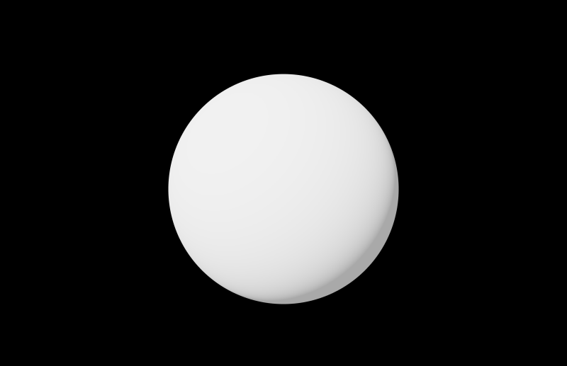
Bonus: Fixing the Shadows
After enabling shadows you’ll discover that the shadow forged by the mesh doesn’t respect geometry displacement. It’s nonetheless from the essential sphere form.
We have to use {custom} depth materials that respects our modifications to the geometry. Let’s repair that:
<mesh geometry={geometry}>
	<CustomShaderMaterial
		ref={materialRef}
		silent
		baseMaterial={MeshPhysicalMaterial}
		vertexShader={vertexShader}
		fragmentShader={fragmentShader}
		uniforms={uniforms}
		roughness={0.56}
		metalness={0.76}
		clearcoat={0}
		ior={2.81}
		iridescence={0.96}
	/>
	{/* Customized depth materials, reusing vertex shader and uniforms */}
	<CustomShaderMaterial
	    ref={depthMaterialRef}
	    baseMaterial={MeshDepthMaterial}
	    vertexShader={vertexShader}
	    uniforms={uniforms}
	    silent
	    depthPacking={RGBADepthPacking}
	    connect="customDepthMaterial"
	/>
</mesh>
That’s it. I added controls so that you can have enjoyable with this demo. Get pleasure from!